F = ke = 125 x 0.2 = 25 N
johnmulu answered the question on April 19, 2017 at 09:31
-
The three springs shown in Figure 5 are identical and have negligible weight. The extension produced on the system of springs is 20 cm.
(Solved)
The three springs shown in Figure 5 are identical and have negligible weight. The extension produced on the system of springs is 20 cm.
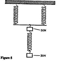
Determine the constant of each spring
Date posted:
April 19, 2017
.
Answers (1)
-
The spiral spring shown in Figure 4 are identical. Each spring has a spring constant k = 300 N/m
(Solved)
The spiral spring shown in Figure 4 are identical. Each spring has a spring constant k = 300 N/m
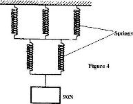
Determine the total extension caused by the 90 N weight. (Ignore the weight of the springs and connecting rods)
Date posted:
April 19, 2017
.
Answers (1)
-
Figure 7 shows a simple electric bell circuit
(Solved)
Figure 7 shows a simple electric bell circuit
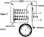
i) Name the parts labeled:
I) D
II) E
ii) When the switch is closed, the hammer hits the gong repeatedly. Explain why?
I) The hammer hits the gong.
II) The hammer hits the gong repeatedly
Date posted:
April 19, 2017
.
Answers (1)
-
Figure 8 shows two parallel thick copper conductors connected to a d.c. power supply. A rider made from a thin copper wire is placed on the conductors
(Solved)
Figure 8 shows two parallel thick copper conductors connected to a d.c. power supply. A rider made from a thin copper wire is placed on the conductors
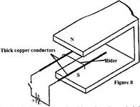
State and explain what is observed on the rider when the switch is closed.
Date posted:
April 19, 2017
.
Answers (1)
-
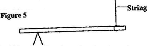
In the set up in Fig. 5, the suspended metre rule in equilibrium balanced by the magnet and the weight shown. The iron core is fixed to the bench.
(Solved)
In the set up in Fig. 5, the suspended metre rule in equilibrium balanced by the magnet and the weight shown. The iron core is fixed to the bench.
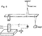
i) State and explain the effect on the metre rule when the switch S, is closed.
ii) What would be the effect of reversing the battery terminals?
iii) Suggest how the set up in figure 5 can be adapted to measure the current flowing in the current circuit.
Date posted:
April 19, 2017
.
Answers (1)
-
Figure 6 shows an athlete lifting weights while standing with the feet apart
(Solved)
Figure 6 shows an athlete lifting weights while standing with the feet apart
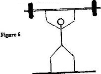
Explain why standing with the feet apart improves the athlete’s stability.
Date posted:
April 19, 2017
.
Answers (2)
-
Figure 3 shows a uniform metre rule pivoted at the 30 cm mark. It is balanced by a weight of 2 N suspended at the 5 cm mark.
(Solved)
Figure 3 shows a uniform metre rule pivoted at the 30 cm mark. It is balanced by a weight of 2 N suspended at the 5 cm mark.
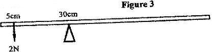
Determine the weight of the metre rule
Date posted:
April 19, 2017
.
Answers (1)
-
Figure 5 shows a uniform bar of length 1.0 m pivoted near one end. The bar is kept in equilibrium by a spring balance as shown.
(Solved)
Figure 5 shows a uniform bar of length 1.0 m pivoted near one end. The bar is kept in equilibrium by a spring balance as shown.
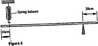
Given that the reading of the spring balance is 0.6 N, determine the weight of the bar
Date posted:
April 19, 2017
.
Answers (1)
-
Figure 3 shows a rectangular block of wood with a hollow section (inside) at the position shown. The block is resting on a Horizontal bench
(Solved)
Figure 3 shows a rectangular block of wood with a hollow section (inside) at the position shown. The block is resting on a Horizontal bench
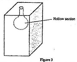
i) State the effect on the stability of the block when the hollow section is filled with water
ii) Explain your answer in (i) above.
Date posted:
April 19, 2017
.
Answers (1)
-
Figure 3 shows two identical trolleys with loads A and B. The loads are identical in shape and size
(Solved)
Figure 3 shows two identical trolleys with loads A and B. The loads are identical in shape and size
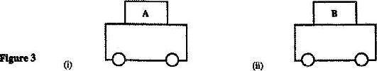
Given that the density of A is greater than that of B, explain why the trolley in Figure 3 (ii) is more stable
Date posted:
April 19, 2017
.
Answers (1)
-
Figure 3 shows two identical hollow spheres. Sphere A is completely filled with the liquid while B is partially filled with identical liquid.
(Solved)
Figure 3 shows two identical hollow spheres. Sphere A is completely filled with the liquid while B is partially filled with identical liquid.
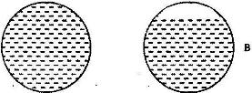
When the two spheres are rolled gently on a horizontal surface, it is observed that the sphere B stops earlier that the sphere A. Explain this observation.
Date posted:
April 18, 2017
.
Answers (1)
-
Figure 2 shows a beaker placed on a bench. A block of ice is placed in the beaker as shown
(Solved)
Figure 2 shows a beaker placed on a bench. A block of ice is placed in the beaker as shown
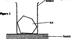
State and explain the change in the stability of the beaker when the ice melts
Date posted:
April 18, 2017
.
Answers (1)
-
Figure 4 shows a uniform metal rod balanced at its centre by different forces.
(Solved)
Figure 4 shows a uniform metal rod balanced at its centre by different forces.
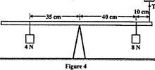
Determine the value of T.
Date posted:
April 18, 2017
.
Answers (1)
-
Figure 5 shows a uniform rod 4 m and of mass 2 kg. It is pivoted 1 m from one end and balanced horizontally by a string attached near the other end
(Solved)
Figure 5 shows a uniform rod 4 m and of mass 2 kg. It is pivoted 1 m from one end and balanced horizontally by a string attached near the other end
Determine the position where a mass of 5 kg should be placed on the rod so that the rod remains horizontally by a string attached near the other end.
Date posted:
April 18, 2017
.
Answers (1)
-
Figure 9 shows a uniform bar in equilibrium under the action of two forces.
(Solved)
Figure 9 shows a uniform bar in equilibrium under the action of two forces.
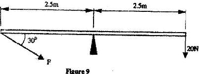
Determine the value of F.
Date posted:
April 18, 2017
.
Answers (1)
-
Figure 4 shows a uniform metre rule of weight I N with two weights of 0.18 N and 0.12 N suspended from its ends.
(Solved)
Figure 4 shows a uniform metre rule of weight I N with two weights of 0.18 N and 0.12 N suspended from its ends.
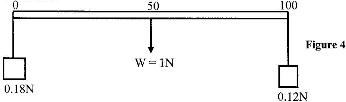
Determine how far from the 0.18 N weight a pivot should be placed in order to balance the meter rule
Date posted:
April 18, 2017
.
Answers (1)
-
Figure 1 shows a vernier calipers being used to measure the internal diameter of a tube
(Solved)
Figure 1 shows a vernier calipers being used to measure the internal diameter of a tube
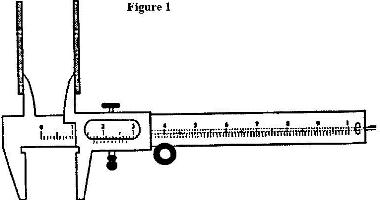
Record the diameter of the tube
Date posted:
April 18, 2017
.
Answers (1)
-
Figure 3 shows part of an experimental set up for estimating the diameter of an oil molecule.
(Solved)
Figure 3 shows part of an experimental set up for estimating the diameter of an oil molecule.
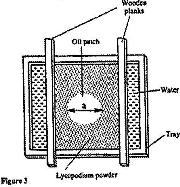
i) Describe how the oil patch is formed.
ii) Describe one method of determining the diameter of the oil drop
Date posted:
April 18, 2017
.
Answers (1)
-
Figure 1 shows a micrometer screw gauge being used to measure the diameter of a ball bearing. A magnified portion of the scale is shown
(Solved)
Figure 1 shows a micrometer screw gauge being used to measure the diameter of a ball bearing. A magnified portion of the scale is shown
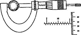
Date posted:
April 18, 2017
.
Answers (1)
-
Figure 1 shows a micrometer screw gauge being used to measure the diameter of a metal rod. The thimble scale has 50 divisions
(Solved)
Figure 1 shows a micrometer screw gauge being used to measure the diameter of a metal rod. The thimble scale has 50 divisions
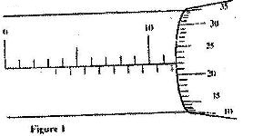
What is the reading shown?
Date posted:
April 18, 2017
.
Answers (1)