- Fig. 7.4(i) shows the basic circuit of a differential amplifier. It consists of two transistors Q
1 and Q
2 that have identical (ideally) characteristics. They share a common positive supply V
CC, common emitter resistor R
E and common negative supply V
EE. Note that the circuit is symmetrical.
- Fig. 7.4(ii) shows the symbol of differential amplifier. The following points may be noted about the differential amplifier:
(i) The differential amplifier (DA) is a two-input terminal device using at least two transistors. There are two output terminals marked 1 (v
out 1) and 2 (v
out 2).
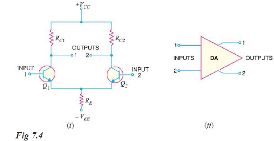
(ii) The DA transistors Q
1 and Q
2 are matched so that their characteristics are the same. The collector resistors (R
C1 and R
C2) are also equal. The equality of the matched circuit components makes the DA circuit arrangement completely symmetrical.
(iii) We can apply signal to a differential amplifier (DA) in the following two ways:
(a) The signal is applied to one input of DA and the other input is grounded. In that case, it is called single-ended input arrangement.
(b) The signals are applied to both inputs of DA. In that case, it is called dual-ended or double-ended input arrangement.
(iv) We can take output from DA in the following two ways:
(a) The output can be taken from one of the output terminals and the ground. In that case, it is called
single-ended output arrangement.
(b) The output can be taken between the two output terminals (i.e., between the collectors of Q
1 and Q
2). In that case, it is called double-ended output arrangement or differential output.
(v) Generally, the differential amplifier (DA) is operated for single-ended output. In other words, we take the output either from output terminal 1 and ground or from output terminal 2 and ground. Any input/output terminal that is grounded is at 0V.
Wilfykil answered the question on
August 15, 2019 at 13:30