-
List two power company equipment and two consumer’s equipment found at a domestic consumer’s intake point.
Date posted:
September 18, 2019
-
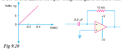
For the differentiator circuit shown in Fig. 9.20, determine the output voltage if the input goes from 0V to 10V in 0.4s. Assume the input voltage changes at constant rate.
Date posted:
August 16, 2019
-
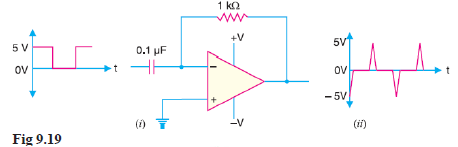
Fig. 9.19 (i) shows the square wave input to a differentiator circuit. Find the output voltage if input goes from 0V to 5V in 0.1 ms.
Date posted:
August 16, 2019
-
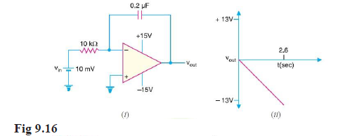
For the integrator circuit shown in Fig. 9.16 (i), how long does it take for the output to reach saturation?
Date posted:
August 16, 2019
-
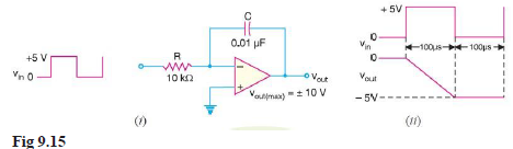
(i) Determine the rate of change of the output voltage in response to a single pulse input to the integrator circuit shown in Fig. 9.15 (i).
(ii) Draw the output waveform.
Date posted:
August 16, 2019
-
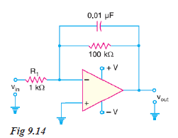
Determine the lower frequency limit (critical frequency) for the integrator circuit shown in Fig. 9.14.
Date posted:
August 16, 2019
-
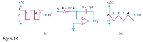
Fig. 9.13 (i) shows the OP-amp integrator and the square wave input. Find the output voltage.
Date posted:
August 16, 2019
-
What is the Critical Frequency of Integrators?
Date posted:
August 16, 2019
-
Two voltages of + 0.6V and – 1.4 V are applied to the two input resistors of a summing amplifier. The respective input resistors are 400 kilo-ohms and 100 kilo-ohms and feedback resistor is 200 kilo-ohms. Determine the output voltage.
Date posted:
August 16, 2019
-
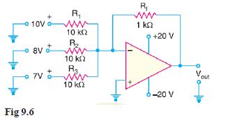
Determine the output voltage for the summing amplifier shown in Fig. 9.6
Date posted:
August 16, 2019
-
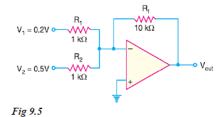
Determine the output voltage for the summing amplifier shown in Fig. 9.5.
Date posted:
August 16, 2019
-
Determine the output voltage for the summing amplifier in Fig. 9.4.

Date posted:
August 16, 2019
-
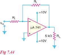
The amplifier in Fig. 7.44 is being used to amplify an input signal to a peak output voltage of 100 mV. What is the maximum operating frequency of the amplifier?
Date posted:
August 16, 2019
-
Determine the maximum operating frequency for the circuit shown in Fig. 7.44. The slew rate is 0.5 V/μs.
Date posted:
August 16, 2019
-
An OP-amp has a gain-bandwidth product of 1.5 MHz. Find the operating bandwidth for the following closed-loop gains (i) ACL = 1 (ii) ACL = 10 (iii) ACL = 100.
Date posted:
August 16, 2019
-
An OP-amp has a gain-bandwidth product of 15 MHz. Determine the bandwidth of OP- amp when ACL = 500. Also find the maximum value of ACL when f2 = 200 kHz.
Date posted:
August 16, 2019
-
Show the schematic symbol of an operational amplifier
Date posted:
August 16, 2019
-
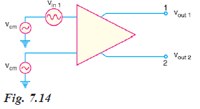
The differential amplifier shown in Fig. 7.14 has a differential voltage gain of 2500 and a CMRR of 30,000. A single-ended input signal of 500 μV r.m.s. is applied. At the same time, 1V, 50 Hz interference signal appears on both inputs as a result of radiated pick-up from the a.c. power system.
(i) Determine the common-mode gain.
(ii) Express the CMRR in dB.
(iii) Determine the r.m.s. output signal.
(iv) Determine the r.m.s. interference voltage on the output.
Date posted:
August 15, 2019
-
A differential amplifier has a voltage gain of 150 and a CMRR of 90 dB. The input signals are 50 mV and 100 mV with 1 mV of noise on each input. Find (i) the output signal (ii) the noise on the output.
Date posted:
August 15, 2019
-
A differential amplifier has an output of 1V with a differential input of 10 mV and an output of 5 mV with a common-mode input of 10 mV. Find the CMRR in dB.
Date posted:
August 15, 2019
-
A certain differential amplifier has a differential voltage gain of 2000 and a common mode gain of 0.2. Determine CMRR and express it in dB.
Date posted:
August 15, 2019
-
Discuss the Double-ended Input Operation of DA
Date posted:
August 15, 2019
-
Explain the Common-mode and Differential-mode Signals
Date posted:
August 15, 2019
-
differential amplifier has an open-circuit voltage gain of 100. The input signals are 3.25 V and 3.15V. Determine the output voltage.
Date posted:
August 15, 2019
-
What are the Limitations of LC and RC Oscillators?
Date posted:
August 15, 2019
-
Give the advantages and disadvantages of Wien Bridge Oscillator
Date posted:
August 15, 2019
-
A phase shift oscillator uses 5 pF capacitors. Find the value of R to produce a frequency of 800 kHz.
Date posted:
August 15, 2019
-
A 1 mH inductor is available. Choose the capacitor values in a Collpitt’s oscillator so that f = 1 MHz and mv = 0.25.
Date posted:
August 15, 2019
-
Determine the (i) operating frequency and (ii) feedback fraction for Collpitt’s oscillator shown in Fig. 6.12.
Date posted:
August 15, 2019
-
What is a Positive Feedback Amplifier — Oscillator?
Date posted:
August 15, 2019