- When only one transistor with associated circuitry is used for amplifying a weak signal, the circuit is known as single stage transistor amplifier.
- A single stage transistor amplifier has one transistor, bias circuit and other auxiliary components. Although a practical amplifier consists of a number of stages, yet such a complex circuit can be conveniently split up into separate single stages. By analyzing carefully only a single stage and using this single stage analysis repeatedly, we can effectively analyse the complex circuit.
How Transistor Amplifies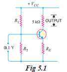
- Fig. 5.1 shows a single stage transistor amplifier. When a weak a.c. signal is given to the base of transistor, a small base current (which is a.c.) starts flowing. Due to transistor action, a much larger (ß times the base current) a.c. current flows through the collector load R
C.
- As the value of R
C is quite high (usually 4 - 10 kilo-ohms), therefore, a large voltage appears across R
C. Thus, a weak signal applied in the base circuit appears in amplified form in the collector circuit. It is in this way that a transistor acts as an amplifier.
- The action of transistor amplifier can be beautifully explained by referring to Fig. 5.1. Suppose a change of 0.1V in signal voltage produces a change of 2 mA in the collector current. Obviously, a signal of only 0.1V applied to the base will give an output voltage = 2 mA × 5 kilo-ohms = 10V. Thus, the transistor has been able to raise the voltage level of the signal from 0.1V to 10V i.e. voltage amplification or stage gain is 100.
Graphical Demonstration of Transistor Amplifier- The function of transistor as an amplifier can also be explained graphically. Fig. 5.2 shows the output characteristics of a transistor in CE configuration. Suppose the zero signal base current is 10 µA i.e. this is the base current for which the transistor is biased by the biasing network.
- When an a.c. signal is applied to the base, it makes the base, say positive in the first half-cycle and negative in the second half cycle. Therefore, the base and collector currents will increase in the first half-cycle when base-emitter junction is more forward-biased. However, they will decrease in the second half-cycle when the base-emitter junction is less forward biased.
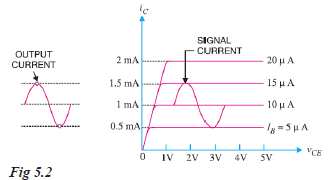
- For example, consider a sinusoidal signal which increases or decreases the base current by 5 µA in the two half-cycles of the signal. Referring to Fig. 5.2, it is clear that in the absence of signal, the base current is 10µA and the collector current is 1 mA.
- However, when the signal is applied in the base circuit, the base current and hence collector current change continuously. In the first half-cycle peak of the signal, the base current increases to 15 µA and the corresponding collector current is 1.5 mA. In the second half-cycle peak, the base current is reduced to 5 µA and the corresponding collector current is 0.5 mA. For other values of the signal, the collector current is in between these values i.e. 1.5 mA and 0.5 mA.
- It is clear from Fig. 5.2 that 10 µA base current variation results in 1mA (1,000 µA) collector current variation i.e. by a factor of 100. This large change in collector current flows through collector resistance R
C. The result is that output signal is much larger than the input signal. Thus, the transistor has done amplification.
Wilfykil answered the question on
August 15, 2019 at 08:18