-
differential amplifier has an open-circuit voltage gain of 100. The input signals are 3.25 V and 3.15V. Determine the output voltage.
(Solved)
differential amplifier has an open-circuit voltage gain of 100. The input signals are 3.25 V and 3.15V. Determine the output voltage.
Date posted:
August 15, 2019
.
Answers (1)
-
What are the Limitations of LC and RC Oscillators?
(Solved)
What are the Limitations of LC and RC Oscillators?
Date posted:
August 15, 2019
.
Answers (1)
-
Give the advantages and disadvantages of Wien Bridge Oscillator
(Solved)
Give the advantages and disadvantages of Wien Bridge Oscillator
Date posted:
August 15, 2019
.
Answers (1)
-
A phase shift oscillator uses 5 pF capacitors. Find the value of R to produce a frequency of 800 kHz.
(Solved)
A phase shift oscillator uses 5 pF capacitors. Find the value of R to produce a frequency of 800 kHz.
Date posted:
August 15, 2019
.
Answers (1)
-
A 1 mH inductor is available. Choose the capacitor values in a Collpitt’s oscillator so that f = 1 MHz and mv = 0.25.
(Solved)
A 1 mH inductor is available. Choose the capacitor values in a Collpitt’s oscillator so that f = 1 MHz and mv = 0.25.
Date posted:
August 15, 2019
.
Answers (1)
-
Determine the (i) operating frequency and (ii) feedback fraction for Collpitt’s oscillator shown in Fig. 6.12.
(Solved)
Determine the (i) operating frequency and (ii) feedback fraction for Collpitt’s oscillator shown in Fig. 6.12.
Date posted:
August 15, 2019
.
Answers (1)
-
What is a Positive Feedback Amplifier — Oscillator?
(Solved)
What is a Positive Feedback Amplifier — Oscillator?
Date posted:
August 15, 2019
.
Answers (1)
-
What is an Oscillatory Circuit?
(Solved)
What is an Oscillatory Circuit?
Date posted:
August 15, 2019
.
Answers (1)
-
Give the advantages of a sinusoidal oscillator
(Solved)
Give the advantages of a sinusoidal oscillator
Date posted:
August 15, 2019
.
Answers (1)
-
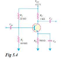
Select a suitable value for the emitter bypass capacitor in Fig. 5.4 if the amplifier is to operate over a frequency range from 2 kHz...
(Solved)
Select a suitable value for the emitter bypass capacitor in Fig. 5.4 if the amplifier is to operate over a frequency range from 2 kHz to 10 kHz.
Date posted:
August 15, 2019
.
Answers (1)
-
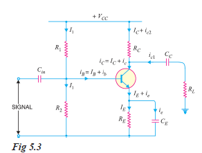
What is the role of emitter bypass capacitor CE in CE amplifier circuit shown in Fig. 5.3 ? Illustrate with a numerical example.
(Solved)
What is the role of emitter bypass capacitor CE in CE amplifier circuit shown in Fig. 5.3 ? Illustrate with a numerical example.
Date posted:
August 15, 2019
.
Answers (1)
-
Show and explain a Practical Circuit of Transistor Amplifier
(Solved)
Show and explain a Practical Circuit of Transistor Amplifier
Date posted:
August 15, 2019
.
Answers (1)
-
A change of 200 mV in base-emitter voltage causes a change of 100 µA in the base current. Find the input resistance of the transistor.
(Solved)
A change of 200 mV in base-emitter voltage causes a change of 100 μA in the base current. Find the input resistance of the transistor.
Date posted:
August 15, 2019
.
Answers (1)
-
What does the performance of a transistor amplifier depend upon?
(Solved)
What does the performance of a transistor amplifier depend upon?
Date posted:
August 15, 2019
.
Answers (1)
-
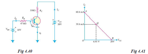
Determine the Q point of the transistor circuit shown in Fig. 4.40. Also draw the d.c. load line. Given ß = 200 and VBE =...
(Solved)
Determine the Q point of the transistor circuit shown in Fig. 4.40. Also draw the d.c. load line. Given β = 200 and VBE = 0.7V.
Date posted:
August 15, 2019
.
Answers (1)
-
In the circuit diagram shown in Fig. 4.39 (i), if VCC = 12V and RC = 6 kilo-ohms, draw the d.c. load line.
(Solved)
In the circuit diagram shown in Fig. 4.39 (i), if VCC = 12V and RC = 6 kilo-ohms, draw the d.c. load line. What will be the Q point if zero signal base current is 20μA and β = 50?
Date posted:
August 15, 2019
.
Answers (1)
-
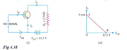
For the circuit shown in Fig. 4.38 (i), draw the d.c. load line.
(Solved)
For the circuit shown in Fig. 4.38 (i), draw the d.c. load line.
Date posted:
August 15, 2019
.
Answers (1)
-
Explain Transistor Load Line Analysis
(Solved)
Explain Transistor Load Line Analysis
Date posted:
August 15, 2019
.
Answers (1)
-
Show the Comparison of Transistor Connections
(Solved)
Show the Comparison of Transistor Connections
Date posted:
August 15, 2019
.
Answers (1)
-
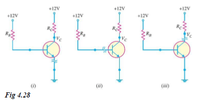
Fig. 4.28 shows the short circuit failures in a transistor. What will be the circuit behaviour in each case ?
(Solved)
Fig. 4.28 shows the short circuit failures in a transistor. What will be the circuit behaviour in each case ?
Date posted:
August 14, 2019
.
Answers (1)