- In common emitter connection, when the input signal voltage increases in the positive sense, the output voltage increases in the negative direction and vice-versa. In other words, there is a phase difference of 180° between the input and output voltage in CE connection. This is called phase reversal.
- The phase difference of 180° between the signal voltage and output voltage in a common emitter
amplifier is known as phase reversal.
Wilfykil answered the question on August 15, 2019 at 08:40
-
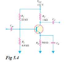
Select a suitable value for the emitter bypass capacitor in Fig. 5.4 if the amplifier is to operate over a frequency range from 2 kHz...
(Solved)
Select a suitable value for the emitter bypass capacitor in Fig. 5.4 if the amplifier is to operate over a frequency range from 2 kHz to 10 kHz.
Date posted:
August 15, 2019
.
Answers (1)
-
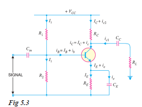
What is the role of emitter bypass capacitor CE in CE amplifier circuit shown in Fig. 5.3 ? Illustrate with a numerical example.
(Solved)
What is the role of emitter bypass capacitor CE in CE amplifier circuit shown in Fig. 5.3 ? Illustrate with a numerical example.
Date posted:
August 15, 2019
.
Answers (1)
-
Show and explain a Practical Circuit of Transistor Amplifier
(Solved)
Show and explain a Practical Circuit of Transistor Amplifier
Date posted:
August 15, 2019
.
Answers (1)
-
Define Single Stage Transistor Amplifier and explain how it works
(Solved)
Define Single Stage Transistor Amplifier and explain how it works
Date posted:
August 15, 2019
.
Answers (1)
-
For a single stage transistor amplifier, the collector load is RC = 2 kilo-ohms and the input resistance Ri = 1 kilo-ohm. If the current...
(Solved)
For a single stage transistor amplifier, the collector load is RC = 2 kilo-ohms and the input resistance Ri = 1 kilo-ohm. If the current gain is 50, calculate the voltage gain of the amplifier.
Date posted:
August 15, 2019
.
Answers (1)
-
If the collector current changes from 2 mA to 3mA in a transistor when collector- emitter voltage is increased from 2V to 10V, what is...
(Solved)
If the collector current changes from 2 mA to 3mA in a transistor when collector- emitter voltage is increased from 2V to 10V, what is the output resistance?
Date posted:
August 15, 2019
.
Answers (1)
-
A change of 200 mV in base-emitter voltage causes a change of 100 µA in the base current. Find the input resistance of the transistor.
(Solved)
A change of 200 mV in base-emitter voltage causes a change of 100 μA in the base current. Find the input resistance of the transistor.
Date posted:
August 15, 2019
.
Answers (1)
-
What does the performance of a transistor amplifier depend upon?
(Solved)
What does the performance of a transistor amplifier depend upon?
Date posted:
August 15, 2019
.
Answers (1)
-
What is the Output from Transistor Amplifier?
(Solved)
What is the Output from Transistor Amplifier?
Date posted:
August 15, 2019
.
Answers (1)
-
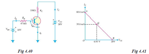
Determine the Q point of the transistor circuit shown in Fig. 4.40. Also draw the d.c. load line. Given ß = 200 and VBE =...
(Solved)
Determine the Q point of the transistor circuit shown in Fig. 4.40. Also draw the d.c. load line. Given β = 200 and VBE = 0.7V.
Date posted:
August 15, 2019
.
Answers (1)
-
In the circuit diagram shown in Fig. 4.39 (i), if VCC = 12V and RC = 6 kilo-ohms, draw the d.c. load line.
(Solved)
In the circuit diagram shown in Fig. 4.39 (i), if VCC = 12V and RC = 6 kilo-ohms, draw the d.c. load line. What will be the Q point if zero signal base current is 20μA and β = 50?
Date posted:
August 15, 2019
.
Answers (1)
-
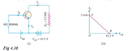
For the circuit shown in Fig. 4.38 (i), draw the d.c. load line.
(Solved)
For the circuit shown in Fig. 4.38 (i), draw the d.c. load line.
Date posted:
August 15, 2019
.
Answers (1)
-
Explain Transistor Load Line Analysis
(Solved)
Explain Transistor Load Line Analysis
Date posted:
August 15, 2019
.
Answers (1)
-
Explain Transistor as an Amplifier in CE Arrangement
(Solved)
Explain Transistor as an Amplifier in CE Arrangement
Date posted:
August 15, 2019
.
Answers (1)
-
Which are the Commonly Used Transistor Connection?
(Solved)
Which are the Commonly Used Transistor Connection?
Date posted:
August 15, 2019
.
Answers (1)
-
Show the Comparison of Transistor Connections
(Solved)
Show the Comparison of Transistor Connections
Date posted:
August 15, 2019
.
Answers (1)
-
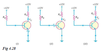
Fig. 4.28 shows the short circuit failures in a transistor. What will be the circuit behaviour in each case ?
(Solved)
Fig. 4.28 shows the short circuit failures in a transistor. What will be the circuit behaviour in each case ?
Date posted:
August 14, 2019
.
Answers (1)
-
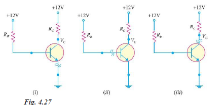
Fig. 4.27 shows the open circuit failures in a transistor. What will be the circuit behaviour in each case ?
(Solved)
Fig. 4.27 shows the open circuit failures in a transistor. What will be the circuit behaviour in each case ?
Date posted:
August 14, 2019
.
Answers (1)
-
A transistor has the following ratings: IC (max) = 500 mA and ßmax = 300.
(Solved)
A transistor has the following ratings: IC (max) = 500 mA and ßmax = 300. Determine the maximum allowable value of IB for the device.
Date posted:
August 14, 2019
.
Answers (1)
-
In a transistor, IB = 68 µA, IE = 30 mA and ß = 440.
(Solved)
In a transistor, IB = 68 µA, IE = 30 mA and ß = 440. Determine the a rating of the
transistor. Then determine the value of IC using both the a rating and ß rating of the transistor.
Date posted:
August 14, 2019
.
Answers (1)