- A differential amplifier (DA) has two inputs so that it can simultaneously receive two signals. The input signals to a DA are defined as :
(i) Differential-mode signals (ii) Common-mode signals
The differential-mode signals are equal in amplitude but 180° out of phase. The common-mode signals are equal in magnitude and have the same phase.
(i)
Differential input: In this mode (arrangement), two opposite-polarity (180° out of phase) signals are applied to the inputs of DA as shown in Fig. 7.10 (i).
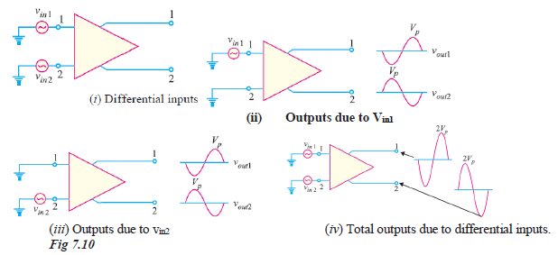
- Each input affects the outputs. Fig. 7.10 (ii) shows the output signals due to the signal on input 1 acting alone as a single-ended input.
- (Note that in all the Figures in Fig. 7.10, the phase of the input signal is given in the circle and the phase shift in the output signal is given at the output terminals. Thus in Fig. 7.10 (ii), the output signal at terminal 1 is 180° out of phase with the input signal. On the other hand, the output signal at terminal 2 is in phase with the input signal.)
- Fig. 7.10 (iii) shows the output signals due to the signal on input 2 acting alone as a single-ended input. Note that in Figs. 7.10 (ii) and (iii), the signals on output 1 are of the same polarity. The same is also true for output 2. By superimposing both output 1 signals and both output 2 signals, we get the total outputs due to differential inputs [See Fig. 7.10(iv)].
- Note that a DA amplifies (v
1 – v
1). For Fig. 7.10 (ii), v
in1 – v
in2 = v
in1 – 0 = v
in1. For Fig. 7.10 (iii),
v
in1 – v
in2 = 0 – v
in2 = –v
in2.
(ii)
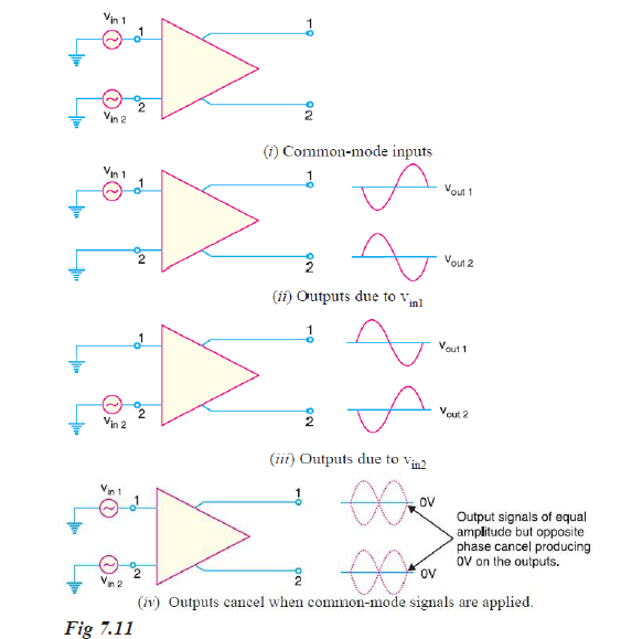
Common-mode input: In this mode, two signals equal in amplitude and having the same phase are applied to the inputs of DA as shown in Fig. 7.11(i).
- Again, by considering each input signal acting alone, the basic operation of DA in this mode can be explained. Fig. 7.11 (ii) shows the output signals due to the signal on only input 1 while Fig. 7.11 (iii) shows the output signals due to the signal on only input 2.
- Note that the corresponding signals on output 1 are of the opposite polarity and so are the ones on output 2. When these are superimposed, they cancel, resulting in zero output voltage as shown in Fig.
7.11 (iv).
- Note also that common-mode signals are rejected by DA. This action is called common-mode rejection. Most of noises and other unwanted signals are common-mode signals. When these unwanted signals appear on the inputs of a DA, they are virtually eliminated on the output.
Wilfykil answered the question on
August 15, 2019 at 13:47